
An RJ45 Copper Transceiver Module (formally known as a Copper SFP/SFP+ Transceiver, commonly called a "Copper Module" or "RJ45 Transceiver") is a hot-pluggable network transceiver that transmits data signals via a standard RJ45 interface and twisted-pair copper cables (e.g., Cat6a, Cat7). It acts as a "bridge" or "translator" between the optical ports on network devices (switches, routers, servers) and traditional copper-based network equipment(PC,IP camera).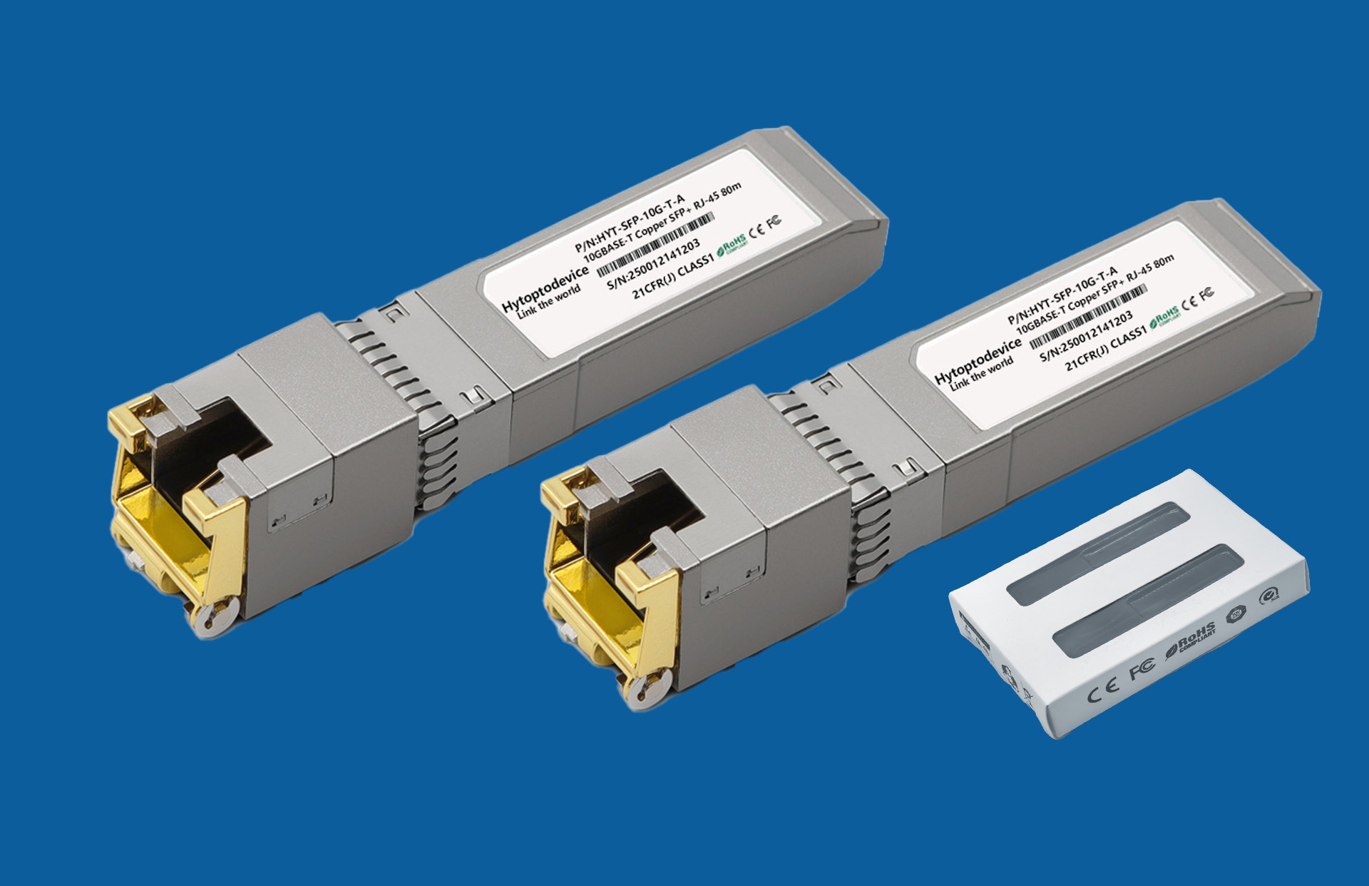
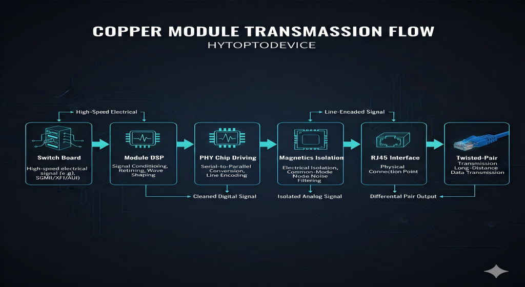
The core function of a copper module is signal media conversion within the device. The specific process is as follows:
Receives Electrical Signal: Receives Low-Voltage Differential Signaling (LVDS) from the switch/router's circuit board.
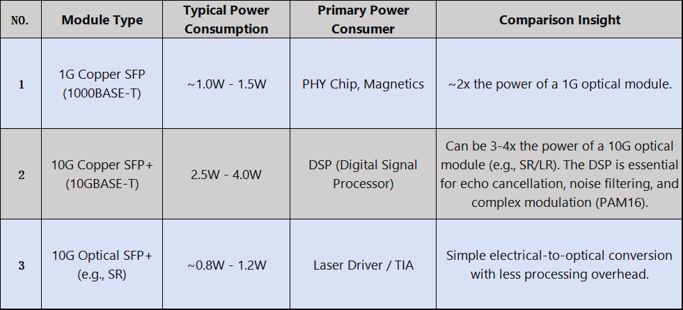
Signal Processing: Processes the signal via an integrated Digital Signal Processor (DSP), performing:
Physical Layer Driving: The signal is driven by a PHY chip and then coupled to the RJ45 interface through magnetics.
Cable Transmission: The signal is transmitted over twisted-pair cables in differential form.
Whether you need the high-performance reliability of Broadcom/Marvell for mission-critical tasks or the efficiency of Realtek for volume deployments, we have the factory-direct capability to deliver.
✅ Custom Chipsets: Marvell, Broadcom, Realtek, and more. ✅ Full Compatibility: Tailored firmware for seamless "Plug & Play" experience. ✅ Source Factory: Direct control over quality and configuration.
The Strategy:
Uplinks: Use 10G optical modules for the core/distribution layer.
Access Layer: Use 2.5G/5G/10G copper modules in access switches to leverage existing cabling and connect to:Wi-Fi 6/6E Access Points requiring >1G uplinks;Modern IP Phones with integrated switches;Power-over-Ethernet (PoE) lighting and sensors.
Key Benefit: Phased Investment & Asset Maximization. Unlocks higher speeds without re-cabling entire buildings.
Why Copper is Essential:
PoE Support: Only copper cabling can deliver PoE (PoE, PoE+, PoE++) to end devices.
Durability: Industrial-grade RJ45 connectors are often preferred over delicate fiber LC connectors in dusty/vibrant environments.
Simplified Troubleshooting: Field technicians are more familiar with copper cable testing.
Key Benefit: Single-Cable Solution for Data & Power in demanding conditions.
3.1.4.5G Fronthaul: CPRI/eCPRI over Ethernet (Copper) Applications
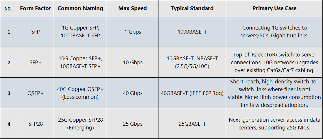
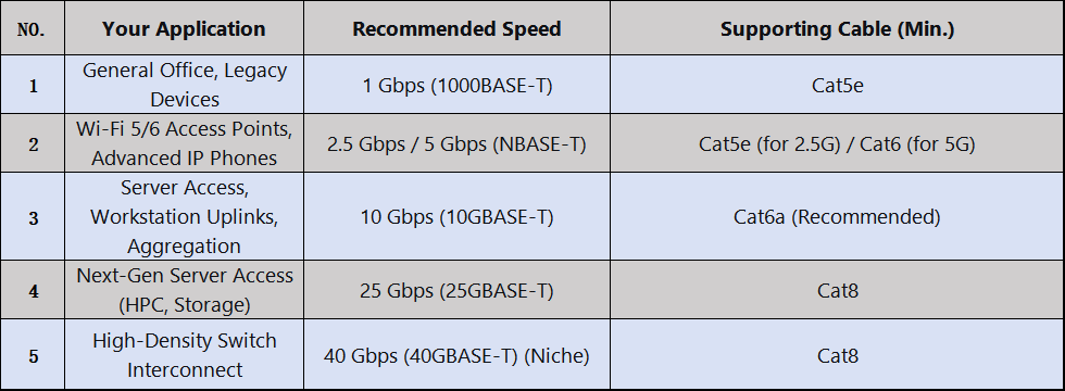
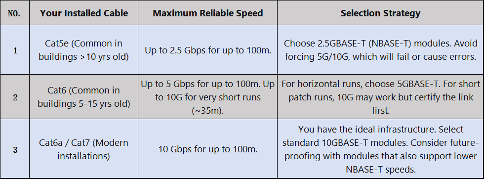
3.2.2.Decision 2: Speed Requirements
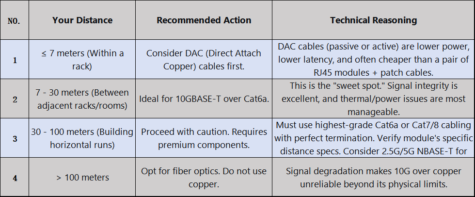
3.2.3.Decision 3: Matching Strategy for Existing Cabling
3.2.4.Decision 4: Cost Model Analysis 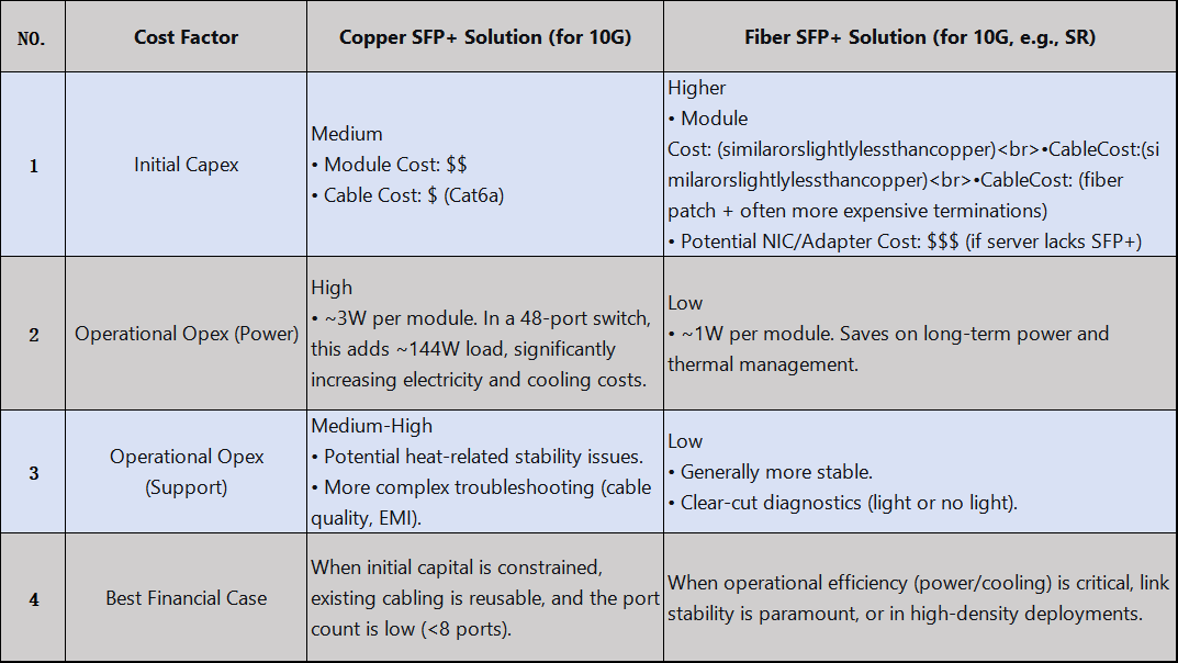
3.3. Practical Compatibility Guide For Rj45 Transceiver Module
Cisco: Has the strictest Electronic ID check. Using non-coded "generic" modules will trigger a "Transceiver unsupported" error. Requires using coded third-party modules or official Cisco ones. The command service unsupported-transceiver can override this but may void support.
Juniper (JuniOS): Generally more flexible. Often accepts MSA-compliant modules but may log a warning. Full management (DOM stats) may require Juniper-branded or smart-coded modules.
Arista (EOS): Similar to Juniper. Good third-party compatibility, with warnings for uncoded modules. Provides commands to explicitly allow unsupported transceivers.
HPE/Aruba: Uses a Cisco-like whitelist. Third-party modules need proper coding.
3.3.2.HYTOPTODEVICE RJ45 Copper SFP Module Compatible Various Brand Device
Backed by over 15 years of dedicated R&D and industry expertise, HYTOPTODEVICE specializes in manufacturing premium Ethernet optical modules engineered for flawless cross-brand compatibility. Our products are rigorously tested with major switch vendors including Cisco, Juniper,HPE, Huawei, H3C, Dell, and Arista—ensuring true plug-and-play performance in diverse network environments.The following chart is the compatible band and its P/N, such as Cisco GLC-T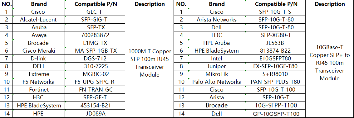
4.How to Use Copper Transceiver Modules (RJ45) and Key Considerations
Copper Transceiver Modules (RJ45 Copper SFP Modules) are one of the most common electrical signal transmission mediums between network devices. Their proper usage and attention to detail directly impact network performance and device longevity. Drawing on 15 years of industry experience, HYTOPTODEVICE has compiled the following practical guidelines and considerations to help you deploy efficiently and maintain stable operations.
Step 1: Pre-Installation Compatibility Verification
Before installation, always use HYTOPTODEVICE's official Compatibility Check Tool or contact technical support to confirm the module model is fully compatible with your switch/router brand and model. We provide a publicly available Module Compatibility List (MCL) for each optical module, supporting auto-recognition on major brands like Cisco, Juniper, and Huawei.
Step 2: Proper Installation Practices
Insert and remove modules gently—avoid applying excessive force or inserting at an angle into the SFP/SFP+ port.
After insertion, listen for a soft "click" to confirm the latch is fully secured.
When connecting Ethernet cables, ensure the RJ45 connector is fully inserted until the locking tab engages.
Step 3: Status Verification and Diagnostics
Use switch command-line or management interface commands, such as show interface transceiver or similar, to confirm:
The optical module is correctly recognized by the system (displaying manufacturer such as “HYTOPTODEVICE” or “OEM” and model information).
Operating temperature and voltage parameters are within normal ranges.
Link status is UP, and negotiated speed meets expectations (e.g., 1000M/2.5G/10G).
4.2.Key Considerations During Use
① Environmental Adaptability Management
While copper modules are rated for industrial temperatures (-40℃ to 85℃), we recommend:
Ensuring proper device ventilation and avoiding prolonged operation above 75℃.
For PoE (Power over Ethernet) applications, monitor power load and heat dissipation conditions.
For outdoor or cabinet deployments, consider using HYTOPTODEVICE industrial-grade ruggedized models.
② Cable and Transmission Distance Matching
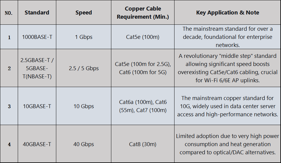
For Gigabit modules (1000BASE-T), use Cat5e or higher-grade cables, with a maximum distance of 100 meters.
For 2.5G/5G modules, use Cat6 cables. For 10G modules (10GBASE-T), Cat6a/Cat7 cables are required.
Avoid severe bending, coiling, or routing cables near strong electromagnetic interference sources.
③ Power and Energy-Saving Configuration
Some switches support EEE (Energy Efficient Ethernet) mode, which may conflict with certain applications; consider disabling it via the switch interface if needed.
When using PoE modules, ensure the switch's power budget meets the requirements of the connected device.
Issue 1: Module Not Recognized by the Switch
✅ Check the compatibility list to confirm model support.
✅ Clean the gold fingers and reinsert, or try a different switch port.
✅ Update the switch firmware to the latest version.
Issue 2: Intermittent Link Drops or Suboptimal Speeds
✅ Replace with high-quality shielded Ethernet cables and verify RJ45 connector craftsmanship.
✅ Disable Auto-Negotiation on the switch port and manually set the speed and duplex mode.
✅ Use HYTOPTODEVICE diagnostic tools to read module DDM information and analyze temperature/voltage anomalies.
Issue 3: Insufficient Transmission Distance or High Bit Error Rate
✅ Confirm cable category and length comply with standards.
✅ Avoid running cables parallel to power lines to reduce interference.
✅ For longer-distance needs, consider HYTOPTODEVICE enhanced transceiver models (supporting up to 150 meters).
Copper transceiver module technology continues to evolve to meet rising demands for higher speeds, better power efficiency, and smarter diagnostics. As networks advance, so do the capabilities of RJ45 SFP modules.
Key Trends:
Multi-Gigabit Adoption: 2.5G/5G/10G BASE-T enabling cost-effective upgrades
PoE++ Support: Delivering up to 90W for high-power devices
Enhanced Diagnostics: Real-time monitoring and predictive maintenance
HYTOPTODEVICE Advantages:
✅ Proven Compatibility – Pre-tested with 1000+ switch models
✅ Future-Ready R&D – Developing 25G/40G BASE-T solutions
✅ Reliable Performance – Industrial-grade quality with 36-month warranty
✅ Expert Support – 24/7 technical assistance and customization options
Make the Smart Choice:
Choosing HYTOPTODEVICE means investing in reliability, compatibility, and innovation. Our copper transceiver modules deliver performance today while evolving for tomorrow's networks.
Get Started Today:
📧 Contact: sale@hyptoptodevice.com
🌐 Learn more:HYTOPTODEVICE RJ45 Copper Module


