Every minor improvement from laser chips to packaging processes can lead to exponential gains in bandwidth.Every frame in a smooth video call, the instantaneous migration of massive data in cloud computing centers, the seamless experience of HD streaming on 5G networks—all rely on an invisible "data highway": optical communication bandwidth.As the technical team at HYTOPTODEVICE, a source factory for optical modules, we work daily with the blueprints and building materials of this highway.
Table of Contents
1.Optical Communication Bandwidth Is The Digital World’s Expressway
1.1Definition:
1.2.Bandwidth:The Digital World's Expressway
2.The Scientific Meaning of Optical Module Bandwidth
3.Bandwidth Evolution: The Technological Journey from 1G to 800G+
4.What Key Factors Shape Optical Communication Bandwidth?
5.How to Increase Bandwidth of Optical Communication
5.1.Increase the Baud Rate (Symbol Rate)
5.2.Use Higher-Order Modulation Formats 5.3.Expand the Number of Parallel Lanes/Channels 5.4.Advanced Packaging and Co-Design 5.5.Enhanced DSP Algorithms 5.6.Improve Component Materials and Design 6.How to Choose the Right Bandwidth? Avoid Overspending & Waste 6.1.The Bandwidth Selection is the Wisdom of Matching Application Scenarios 6.2.Core Principle: Match the Scenario 7.Future Outlook: The Next Decade of Bandwidth Technology1.Optical Communication Bandwidth Is The Digital World’s Expressway 1.1Definition:
Optical communication bandwidth refers to the maximum data-carrying capacity of a fiber-optic communication system, typically measured in bits per second (bps), such as Gbps or Tbps. It determines how much data can be transmitted through an optical network in a given time and is a core metric for assessing system performance.
1.2.Bandwidth:The Digital World's Expressway Think of bandwidth as the number of lanes on a highway. A two-lane highway and an eight-lane highway have vastly different capacities—and so does optical communication bandwidth.
It determines not only the "speed limit" of data transmission but also the "simultaneous throughput capacity"—the core difference between bandwidth and data rate.
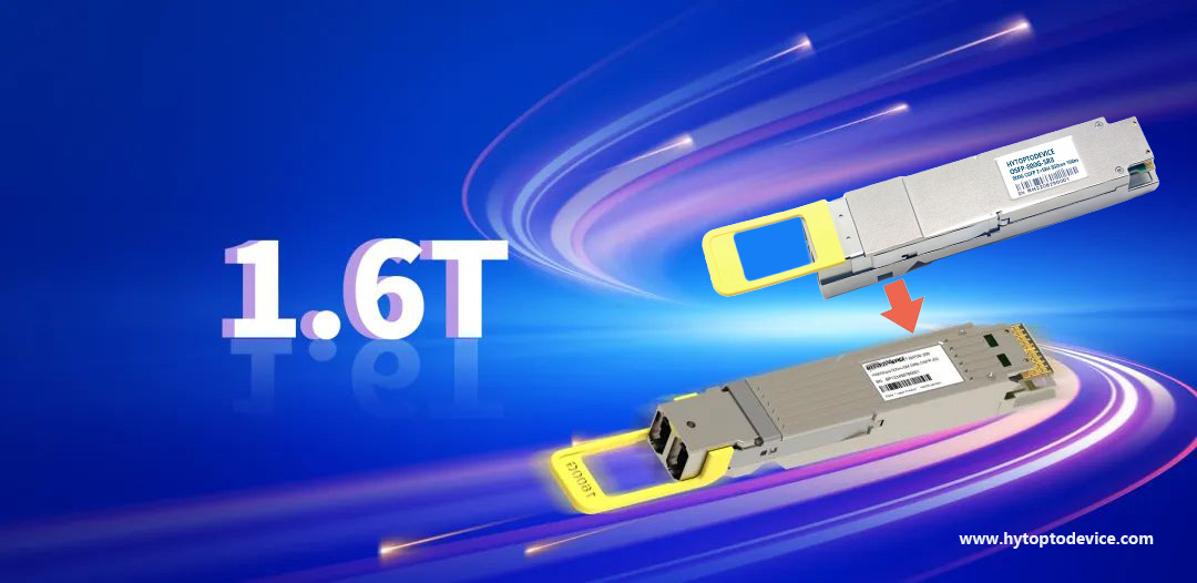
In optical communications, bandwidth units have evolved from MHz and GHz to the THz era, with each order-of-magnitude leap marking a technological revolution.
 2.The Scientific Meaning of Optical Module Bandwidth
Bandwidth refers to the "frequency range" in physics and the "data transmission capacity" in communications. For optical modules, it is the highest modulation frequency range the system can effectively transmit.
When clients ask, "Why doesn’t my 100G optical module achieve its theoretical throughput?" the answer often lies in the nuances of bandwidth limitations.
True bandwidth performance isn’t a single metric but the result of multiple technical dimensions working in harmony. According to factory test data, optical modules with the same nominal data rate can vary by over 30% in effective bandwidth, stemming from the following seven key factors.
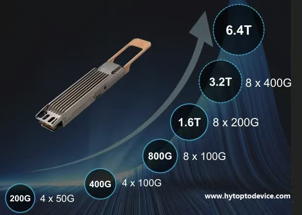
3.Bandwidth Evolution: The Technological Journey from 1G to 800G+ Bandwidth improvement is not achieved overnight. Each generational leap from early 1G to today’s
800G has involved breakthroughs across the following seven factors mentioned.
When transitioning from 40G to 100G, parallel technology (e.g., 4×25G) served as an interim solution. Advancing to
400G required "more efficient modulation" (like PAM4) and "wider channels" (e.g., 100G baud rates).
HYTOPTODEVICE has witnessed each technological transition. Our optical module production lines have upgraded from 10G to 100G, and now to 400G/800G—each upgrade representing a comprehensive enhancement in our control over the following seven key factors.
 4.What Key Factors Shape Optical Communication Bandwidth?
As optical module speeds increase, such as 800G, 1.6T, and even higher, bandwidth has become a primary bottleneck in optical module design. then what key factors influence and limit the optical communication bandwidth?
4.1.Light Source Characteristics – Where Signals Are Born The laser is the "heart" of an optical communication system, and its characteristics directly determine the bandwidth ceiling. Spectral purity, linewidth, modulation bandwidth, and wavelength stability are the four core metrics.
In HYTOPTODEVICE’s lab, we screen every laser chip using "high-precision spectral analysis". High-quality directly modulated lasers (DML) can achieve over 25 GHz modulation bandwidth, while electro-absorption modulated lasers (EML) can exceed 40 GHz.
Wavelength stability is particularly critical for wavelength-division multiplexing (WDM) systems. Our tests have shown that a ±0.1 nm wavelength drift in an 80-channel DWDM system can cause a 3% loss in bandwidth efficiency.
4.2.Modulation Techniques – The Art of Encoding Information Modulation is how electrical signals are "translated" into optical signals. Non-return-to-zero (NRZ) is like the "dots and dashes" of Morse code—simple and reliable but inefficient.
PAM4 modulation is revolutionary because it adds two intermediate levels, transmitting twice the information at the same symbol rate. However, this introduces challenges: distinguishing four levels requires greater precision and imposes stricter signal-to-noise ratio requirements.
In factory production, "eye diagram testing" for PAM4 optical modules is far more stringent than for NRZ. We’ve invested in high-precision bit error rate testers to ensure each level meets specifications.The eye diagram is a comprehensive metric for evaluating the performance of high-speed optical modules. Insufficient bandwidth directly and measurably degrades eye diagram quality.
Here is the specific mechanism of impact:
-
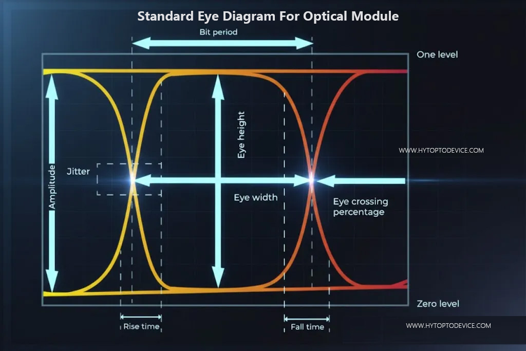
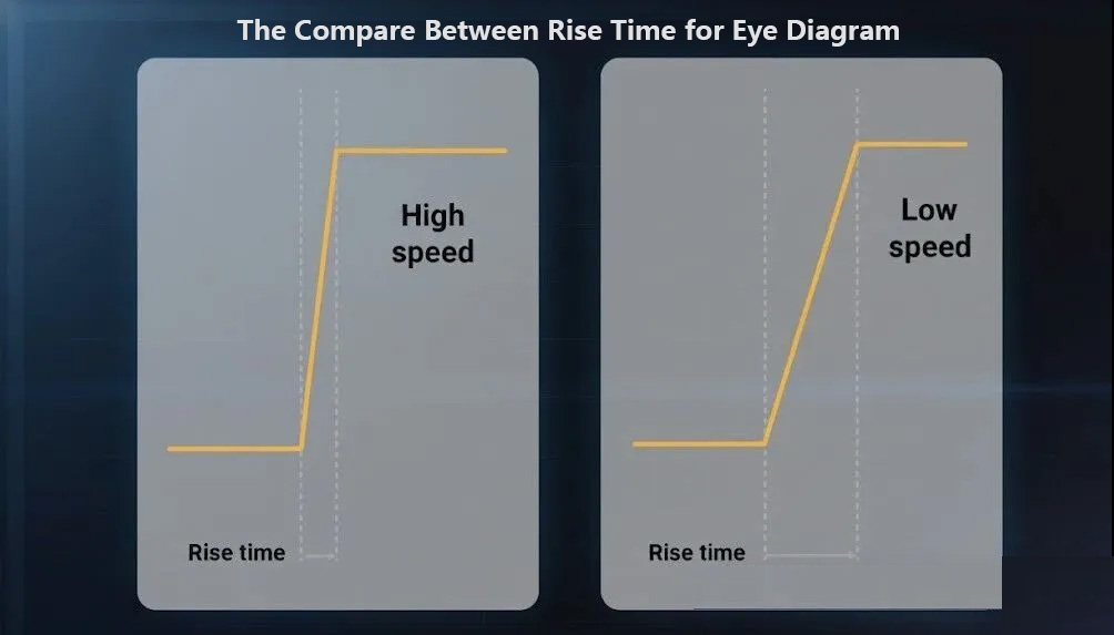
Slowed Signal Rise/Fall Times: Insufficient bandwidth acts like a low-pass filter, attenuating the high-frequency components of the signal. This causes the signal's rising and falling edges to become gradual and rounded. In the eye diagram, this manifests as the left and right "eye walls" collapsing inward, reducing the horizontal eye opening.
The Ideal Standard Eye Diagram :
The left chart below shows a shorter rise time and a higher bandwidth, while the right chart shows a lower rise time:
-
Increased Inter-Symbol Interference (ISI): Slow edges cause the "tail" of one bit to spill into the time slot of adjacent bits, creating Inter-Symbol Interference. This pulls down the voltage level of "1s" and lifts the level of "0s". On the eye diagram, this appears as a thickening of trace layers in the vertical direction, reducing the vertical eye height and making the eye appear blurry and closed.
-
Added Jitter: Bandwidth limitations contribute to deterministic jitter, specifically Data-Dependent Jitter (DDJ). The edge transition speed varies depending on the preceding bit pattern, causing further narrowing of the horizontal eye opening.
An ideal, high-bandwidth system produces an eye diagram that is open, clear, and rectangular. See the above. An eye diagram from a bandwidth-limited system is closed, blurred, and diamond-shaped or slit-like. Its key metrics—Eye Height and Eye Width—are significantly degraded, directly indicating a higher Bit Error Rate probability.
In essence: Bandwidth is the physical foundation that determines the eye diagram's shape. Insufficient bandwidth "squeezes" the eye from both the time domain (edge speed) and amplitude domain (ISI), causing an overall degradation in quality.
4.3.Photodetectors – The Receiving End of Signals A detector’s "response bandwidth" determines the highest frequency signal it can receive. High-speed detectors require bandwidths exceeding 30 GHz to support 100G PAM4 applications.
We often face the trade-off between "sensitivity and bandwidth". Higher bandwidth typically means greater noise, requiring careful design balance. InGaAs detectors excel in the 1550 nm band, while silicon detectors are more cost-effective at 850 nm.
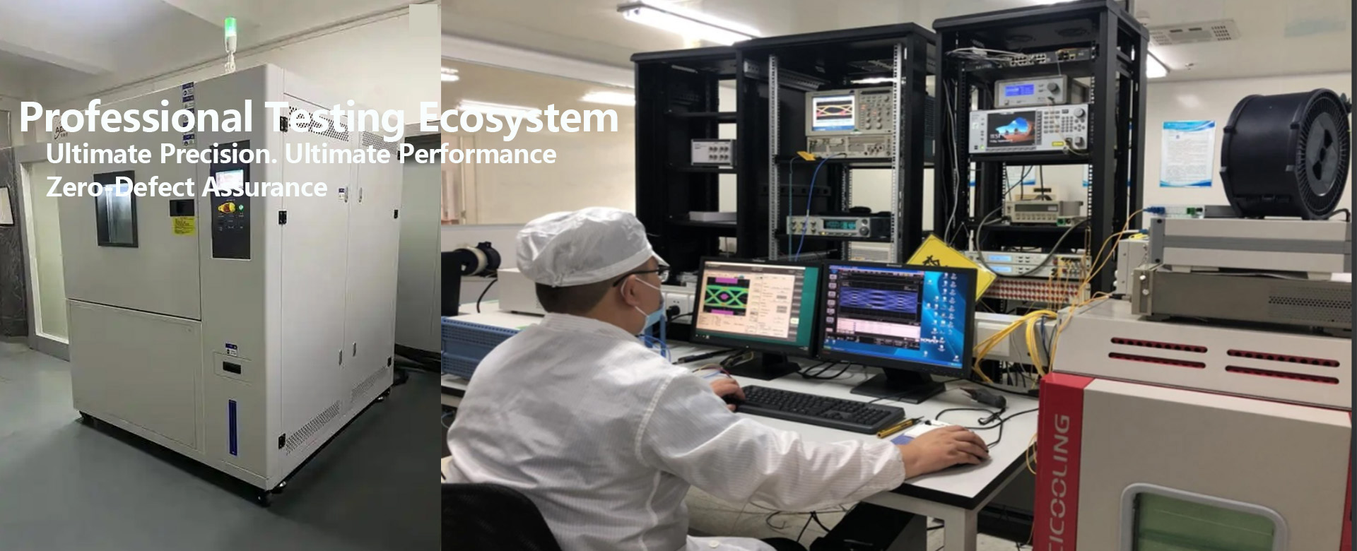
On HYTOPTODEVICE’s production line, every detector undergoes "full-temperature-range bandwidth testing" to ensure consistent performance from -40°C to 85°C.
 4.4.Fiber Transmission Characteristics – The Limitations of the Medium
 Fiber is not a perfect transmission medium. Dispersion effects cause different frequencies of light to travel at different speeds, leading to pulse spreading—a major factor limiting long-distance bandwidth.
Chromatic dispersion and polarization mode dispersion in single-mode fiber must be compensated. In factory testing, we simulate fiber transmission environments up to 80 km to verify an optical module’s dispersion tolerance.
Nonlinear effects become significant at high power levels, akin to vehicles interfering with each other on a busy highway. Self-phase modulation, four-wave mixing, and other phenomena severely degrade signal quality and limit maximum usable power.
4.5.Packaging and Interconnection – The Invisible Bottlenecks Packaging is not just a protective shell; it is the critical interface for electrical-optical-electrical conversion. Parasitic parameters—unwanted capacitance and inductance—act as low-pass filters, limiting high-frequency signals.At HYTOPTODEVICE, we employ "3D electromagnetic field simulations" to optimize packaging designs. By adjusting bond wire lengths and pad layouts, we’ve reduced packaging-induced bandwidth loss from 20% to below 5%.
Thermal management, often overlooked, is vital. Our test data show that for some optical modules, bandwidth can drop by 8% for every 10°C temperature increase. Therefore, we’ve designed "active temperature control" systems for high-speed modules.
Connectors are equally critical, as each interface can be a point of signal attenuation. By upgrading from UPC to APC connectors, we’ve improved return loss from -40 dB to -60 dB, reducing reflection-induced bandwidth impact.
4.6,Electronic Component Performance – The System’s Nervous System Driver chips are like the "nervous system" of an optical module; their slew rate and bandwidth directly affect modulation speed. Leading driver chips on the market now offer bandwidths exceeding 70 GHz.
The jitter performance of Clock and Data Recovery (CDR) circuits determines signal synchronization accuracy. A 1 ps timing error can significantly increase the bit error rate in a 56 GBaud system.
We collaborate deeply with chip suppliers, engaging from the design phase to ensure "co-optimization" of electronic and optical components. This integration capability is a core strength of HYTOPTODEVICE.
4.7.System-Level Optimization – The Whole Exceeds the Sum of Its Parts When individual component performance approaches physical limits, system-level optimization becomes key to bandwidth enhancement. Forward Error Correction (FEC) is like adding "error-correcting codes" to data transmission, trading slight redundancy for greater reliability.
Modern optical modules commonly use soft-decision FEC, providing up to 11 dB of coding gain—equivalent to tripling the transmission distance.
Digital Signal Processing (DSP) algorithms can compensate for various transmission impairments like dispersion and nonlinearities. Our R&D team has developed adaptive equalization algorithms that automatically optimize parameters for different fiber conditions.
Multi-dimensional multiplexing is the future. Beyond wavelength-division multiplexing, we are researching space-division multiplexing (using multi-core fibers) and mode-division multiplexing (using few-mode fibers)—technologies that could increase single-fiber capacity tenfold.
4.8.
Thermal Management
Higher speeds generate more heat in a confined module form factor. Temperature fluctuations affect laser wavelength (drift) and component performance, necessitating robust and power-hungry thermal control.
Thermal management imposes a fundamental, systemic limit on bandwidth:
-
A Performance Degrader: Heat directly destabilizes the precise operating conditions (wavelength, bias point) required by core photonic components for high-bandwidth signaling.
-
A Power Budget "Tax": The energy required to remove heat consumes the limited power envelope, starving the DSP and drivers of the power they need to process more bits.
-
A Physical Bottleneck: The fiber optical module's fixed size sets a hard limit on heat dissipation capacity, thereby capping the achievable power density and bandwidth density.
-
The Root of Reliability & Cost: Heat is the primary accelerator of device aging and failure. To ensure reliability at high temperatures, systems must be derated (operate at lower power/bandwidth) or incorporate expensive cooling solutions, increasing cost.
Therefore, the race to develop next-generation optical modules (1.6T and beyond) is, to a large extent, a race in "thermal design" and "energy efficiency." The core challenge is to generate and process more bits with less power and to efficiently remove the resultant heat. Breaking the bandwidth bottleneck is inseparable from conquering the thermal bottleneck.
5.How to Increase Bandwidth of Optical Communication
5.1.Increase the Baud Rate (Symbol Rate)
Pushing the fundamental speed of the individual lane (e.g., from 50 GBaud to 130+ GBaud). This requires advances in all underlying component technologies (lasers, modulators, detectors, drivers, TIAs).
5.2.Use Higher-Order Modulation Formats
-
Moving from simple OOK/NRZ (1 bit per symbol) to PAM4 (2 bits per symbol), and potentially to PAM8 or coherent formats like QPSK/16-QAM (multiple bits per symbol) within the same baud rate. This is a primary path for next-generation modules (e.g., 1.6T).
5.3.Expand the Number of Parallel Lanes/Channels
- Spatial Multiplexing: Use more optical fibers/wavelengths in parallel. For example, 1.6T modules are expected to use 16 x 100G electrical lanes.
- Wavelength Division Multiplexing (WDM): Pack multiple wavelengths into a single fiber lane. Co-packaged optics (CPO) and silicon photonics enable dense integration of these multi-wavelength engines.
5.4.Advanced Packaging and Co-Design
- Co-Packaged Optics (CPO): Moves the optical engine very close to the ASIC, drastically reducing the lossy and power-hungry electrical channel. This is critical for 1.6T+.
- Silicon Photonics (SiPh): Enables high-density, low-cost integration of modulators, detectors, and WDM components on a single chip, improving bandwidth density and scalability.
5.5.Enhanced DSP Algorithms
- Develop more power-efficient and higher-performance DSP algorithms (e.g., probabilistic shaping, advanced equalization, nonlinear compensation) to extract maximum capacity from the available hardware.
5.6.Improve Component Materials and Design
- Develop new materials (e.g., thin-film lithium niobate modulators) and device designs (e.g., high-bandwidth electro-absorption modulated lasers) to push the intrinsic bandwidth of core optical components.
6.How to Choose the Right Bandwidth? Avoid Overspending & Waste
6
.1.The Bandwidth Selection is the Wisdom of Matching Application Scenarios
Higher bandwidth does not suit all scenarios. Data center interconnects demand "low latency and high density", while telecom long-haul transmission emphasizes "long distance and high reliability".
We often advise clients: "Don’t pay for bandwidth you don’t need." A common mistake is using a 400G optical module for a server connection that only requires 100G, resulting in 70% wasted performance and unnecessary power consumption.
6.2.Core Principle: Match the Scenario
Never pay for bandwidth you don’t need. Cost, power, and complexity rise sharply with speed. Overspecifying hurts ROI.
Key Scenarios & Selection Guide:
| NO. |
Scenario |
Primary Needs |
Bandwidth Consideration |
Common Pitfall |
| 1 |
Data Center Intra-Connect |
Low latency, high density, low power |
Match server access speed and switch oversubscription. Use 25G/100G/200G for access, 400G/800G for spine/leaf. |
Using 400G to connect a 25G server → >70% bandwidth idle, double power waste. |
| 2 |
Data Center Inter-Connect (DCI) |
High capacity, medium reach, cost-sensitive |
Plan based on growth curve. Adopt 100G/400G, evolving to 800G. Balance cost-per-bit and distance. |
Deploying bleeding-edge tech too early (e.g., 1.6T) → high cost, immature ecosystem. |
| 3 |
Telecom Long-Haul |
Long reach, high reliability, standardization |
Limited by fiber loss/dispersion. Use coherent 400G/800G (Open ZR+). |
Using ultra-long-haul modules for <80km links → paying 30%+ premium for unused performance. |
| 4 |
Enterprise/Campus |
Stability, easy management, long lifecycle |
Conservative evolution. Choose mature 10G/25G/100G with 20-30% headroom. |
Chasing data-center-level low latency → over-complicated architecture, high OpEx. |
HYTOPTODEVICE offers "bandwidth consultation" services, recommending the most suitable optical module solutions based on specific application scenarios, transmission distances, and future expansion plans.
7.Future Outlook: The Next Decade of Bandwidth Technology The bandwidth race never ends. Terahertz communications will expand usable spectrum from a few THz today to dozens of THz. Silicon photonic integration will combine multiple functions at the chip level, reducing interconnect losses.
The integration of artificial intelligence will enable "intelligent bandwidth management", allowing systems to dynamically adjust operating modes and parameters based on real-time traffic, optimizing bandwidth utilization.
In HYTOPTODEVICE’s R&D roadmap, we are developing "1.6T optical module" technology, which requires breakthroughs across all seven factors. We believe future bandwidth improvements will depend more on "system-level innovation" than advancements in individual components.
Reference Source: OSFP-400G-SR4 Optical Transceiver OSFP-800G-SR8 Optical Module 100 Gigabit Ethernet
800G-1.6T Optical Module Evolution