If you've worked in network engineering long enough, you've likely come across a common, pragmatic practice: using an optical transceiver rated for 40km to establish a reliable 20km link. On the surface, this might seem like overkill or an unnecessary expense. Why not just use a 20km module? HYTOPTODEVICE, a manufacturer of professional optical modules for many years, serves thousands of customers and has participated in more than 500 engineering projects. will elaborate on this topic.
Table of Contents: 一、What is Optical Module Transmission Distance? 二、Key Factors Influencing Real-World Transmission Distance 三、How to Calculate the Transmission Distance of an Optical Module? 四、Conclusion: Choosing Wisely Why is the 40km Optical Module Used for 20km?The straightforward answer is link budget margin and reliability. In the real world, a fiber link is never perfect. It's a chain of potential weak points: too many connectors (adapters), suboptimal fusion splices, aging or lower-quality fiber cables, and unexpected bends. Each of these introduces insertion loss, eating into the total power budget of fiber optic transceiver available to get the signal from Point A to Point B. By using a 40km module on a 20km link, engineers build in a significant power safety margin. This "headroom" compensates for real-world imperfections and ensures stable, error-free transmission over the intended distance, even as the link degrades slightly over time.
This practice perfectly illustrates that an optical transceiver module's rated distance is a theoretical maximum under ideal lab conditions. The actual achievable distance is a complex equation. Let's delve into the core concepts and the key factors that truly determine how far your data can travel on a beam of light.
一、What is Optical Module Transmission Distance? Simply put, it's the maximum distance over which an fiber network transceiver can transmit data with an acceptable bit error rate (BER). As light travels through fiber, it weakens and disperses. Different wavelengths of light are affected differently, leading to the common classification of modules by their designed reach:
· Short Reach (SR): Typically 2km and below.
· Medium Reach (MR/LR): Commonly 10km to 20km.
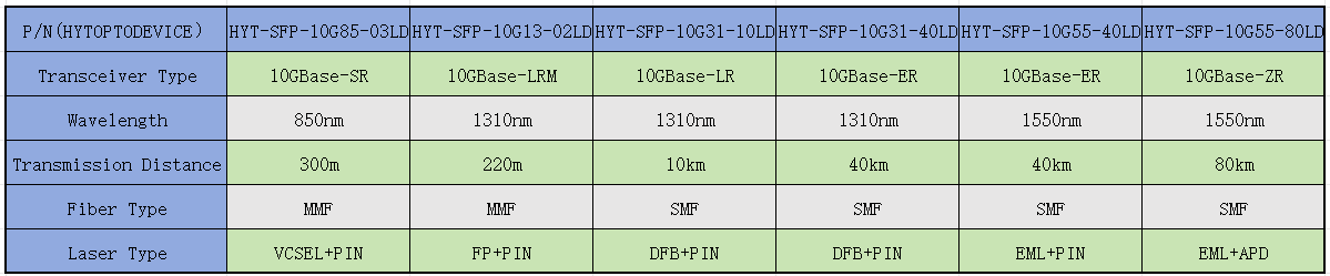
· Long Reach (LR/ER): 40km and beyond (e.g., 40km, 80km, 120km).
These classifications about optical transceiver are directly tied to the technology inside the module, primarily the light source.
二、Key Factors Influencing Real-World Transmission Distance
1. The Light Source: The Heart of the Matter
The light source inside the optical transceiver is crucial for photoelectric signal conversion, and its quality directly affects the transmission distance. this is the most critical component.
Typically, fiber optical modules use light-emitting diodes (LEDs) or laser diodes as the light source.
In the early days, Light Emitting Diodes (LEDs) were once used as light sources, but they had many drawbacks: their data rates were limited to 10 Mb/s–100 Mb/s, transmission distances reached only a few hundred meters—typically not exceeding 2 kilometers—and signal stability was poor. As a result, LEDs have been largely phased out. They were primarily used in early local area networks (LANs).
In contrast, laser diodes support transmission over both multi-mode and single-mode fiber, accommodating data rates from low speed to ultra-high speed and covering distances ranging from a hundred meters to over a hundred kilometers. This versatility has made laser diodes the absolute mainstream technology covering all modern communication scenarios.
The type of laser diode directly dictates the possible reach.
· VCSELs: Used in multi-mode modules for very short distances (up to ~500m). Their wider spectral width limits long-haul use.
· FP Lasers: Affordable but have a broad spectrum, causing high chromatic dispersion, which severely limits distance in single-mode fiber.
· DFB Lasers: The workhorse for 10km, 20km, and 40km applications. Their extremely narrow, single-wavelength output minimizes chromatic dispersion, enabling longer reaches.
· EML Lasers: Integrate a DFB laser with an external modulator. They achieve near-zero chirp (unwanted wavelength shifting during modulation), making them essential for 80km+ distances where dispersion is the primary enemy.
2.Chromatic Dispersion:
Fiber optic dispersion refers to the phenomenon in which light signals of different frequencies travel at varying speeds within an optical fiber, causing them to arrive at the receiving end at different times. This results in pulse broadening and ultimately leads to signal distortion.
Dispersion is one of the critical factors limiting transmission distance. DFB and EML lasers combat this with their ultra-narrow spectra. A 40km SFP+module uses a laser with much higher dispersion tolerance than a 10km SFP+ transceiver. By employing technologies such as fiber dispersion compensation modules, dispersion can be effectively mitigated, thereby extending the transmission range.
3. Attenuation (Loss): The Signal Fade
Fiber optic loss refers to the energy attenuation of an optical signal during transmission through an optical fiber, primarily including absorption loss, scattering loss, and bending loss. This is the phenomenon of the optical signal gradually weakening during transmission. Loss comes from:
· Intrinsic Fiber Loss: Absorption and scattering in the glass itself. This is why we use specific "windows" like 1310nm and 1550nm, where fiber is most transparent.
· Insertion Loss: The real-world killer. Every connector, splice, and bend adds loss. A 20km link with 5 poor connectors can have more total loss than a clean 30km link. This is the primary reason for the 40km-for-20km strategy—to have enough output power to overcome this "dirty" link loss.
The lower the fiber optic loss, the less energy is lost during transmission, thus enabling longer transmission distances.
4. Transmission Rate: The Speed-Distance Trade-off
Transmission rate refers to the speed at which an optical module transmits data. Higher transmission rates require higher light source power and lower losses to ensure that the signal is not distorted during transmission.
Higher data rates (e.g., moving from 1G to 10G to 100G) use faster modulation, which makes the signal more susceptible to both dispersion and attenuation. A module designed for 10G at 40km may only reach 20km at 25G on the same fiber. Higher rates often require more advanced, dispersion-tolerant light sources (like EMLs over DMLs).
5. Operating Environment: The Hidden Variable
Environmental conditions such as temperature, humidity, and air pressure also affect the transmission distance of optical modules. High temperature, high humidity, and high air pressure exacerbate fiber attenuation and dispersion, thus reducing transmission distance.
Temperature fluctuations cause the laser's wavelength to drift and can increase its internal noise (Relative Intensity Noise - RIN). A high-quality, temperature-controlled 40km module will maintain stable performance from -5°C to 70°C, whereas a cheaper module might fail or generate errors at temperature extremes, effectively reducing its reliable reach.
Therefore, in harsh environments, appropriate protective measures are necessary to ensure the performance of optical modules.
三、How to Calculate the Transmission Distance of an Optical Module?
Theoretically, the transmission distance of an optical module can be roughly estimated using the following formula:
Transmission Distance = | Minimum Transmit Power - Receiver Sensitivity | / Optical Attenuation Coefficient However, in practical engineering applications, it is necessary to consider other factors within the optical transmission system that can affect the module's reach and perform a comprehensive calculation.
Example:If an optical module has a transmit power range of -5 to -9 dBm, a receiver sensitivity of -24 dBm, and operates at a wavelength of 1310 nm, what is the minimum achievable transmission distance?
Answer:
Optical attenuation coefficient for 1310 nm is generally taken as 0.45 dB/km.
· When transmit power = -5 dBm:
|(-24) - (-5)| / 0.45 ≈ 42 km
· When transmit power = -9 dBm:
|(-24) - (-9)| / 0.45 ≈ 33 km
Additionally, when calculating optical power budgets and actual attenuation, insertion losses from optical connectors and adapters must be included. Typically, an additional 0.5 dB per port should be factored into the calculation.
四、Conclusion: Choosing Wisely
The rated distance on an fiber optical module is a guideline, not a guarantee. It represents performance under controlled conditions with a pristine fiber link.
When designing a network link, you must calculate the total link budget:
[Transmitter Power] - [Receiver Sensitivity] > [Fiber Attenuation] + [Connector/Splice Losses] + [Safety Margin]
The "safety margin" (typically 3dB or more) is your insurance against future degradation. Using a higher-powered, longer-reach module (like a 40km for a 20km run) is a proven method to build this margin in, ensuring network resilience and reducing future headaches.
Understanding the interplay of light sources, dispersion, loss, and real-world conditions empowers you to select the right tool for the job, guaranteeing a network that is not just functional, but robust and reliable for years to come. HYTOPTODEVICE is a professional provider of optical communication solutions. Please feel free to contact us if you have any questions.