
A dead module is easy. It fails cleanly, you swap it, and you move on. An intermittent module — especially one that passes initial bring-up — does not fail cleanly. This is one of the most time-consuming problems in optical networking procurement, because the failure mode is ambiguous by design.
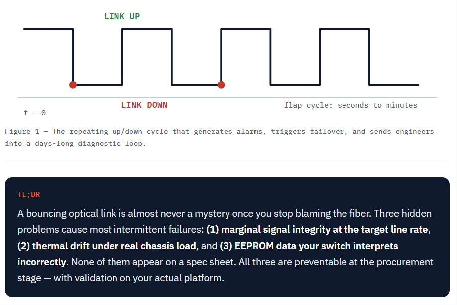
Link up, link down, link up again. That repeating cycle produces alarms, triggers failover, and sends engineers into a diagnostic loop that can run for days before anyone suspects the transceiver itself. The module gets treated as a fiber issue, a switch port issue, an SFP cage issue, a cable plant issue. The module sits in the clear while the team chases everything around it.
In the cases we see, once the surrounding plant checks out clean, the cause is almost always one of three things. None of them show up on a spec sheet. None of them are visible until the module is under real load, in real thermal conditions, on the actual target platform.
Third-party modules that were not validated at the target line rate produce subtle signal integrity problems. At 10G, small deviations in transmit power or receive sensitivity often go unnoticed. At 100G and above, those deviations compound across lanes: a 100G QSFP28 link carries four 25G NRZ lanes, and a 400G link carries PAM4 signals across four or eight lanes.
PAM4 signaling at 400G is significantly less forgiving than NRZ at 10G. PAM4 encodes two bits per symbol in four amplitude levels, so the vertical eye opening is far smaller — the signal-to-noise budget is roughly 9.5 dB tighter than NRZ at the same symbol rate. What a datasheet calls a pass can still be a link that only works when everything else is perfect.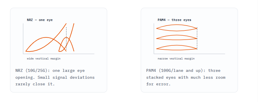
A module that reads within spec on a basic DDM readout can still be producing marginal eye diagrams that the switch ASIC struggles to lock onto under real traffic load. The failure rarely appears while the port is idle.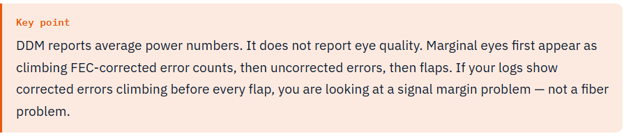
Hidden Cause 2 — Thermal Drift Under Real Load
A module may link up cleanly at ambient temperature during lab testing. In a fully loaded chassis — with adjacent ports saturated and switch airflow partially blocked — the operating temperature of that module climbs. The laser bias current shifts. The transmit power moves outside the acceptable window.
The link starts dropping. But only during peak traffic windows, which is when engineers are least available to troubleshoot it. That timing pattern — clean at night, flapping at noon — is the signature of thermal drift, not of a random hardware fault.
DDM and DOM give you a real-time snapshot of exactly those values: case temperature, transmit power, receive power, and laser bias current. If your supplier cannot provide modules with full DDM support, you lose the only in-band diagnostic tool that would show you the drift is happening.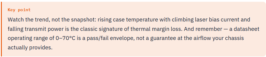
Switch vendors read module EEPROM fields to make decisions about port configuration, FEC negotiation, and alarm thresholds. A module programmed with generic or loosely matched EEPROM data can cause the switch to apply the wrong FEC mode, set incorrect receive-power thresholds, or trigger phantom alarms that produce link resets.
The module is not broken. The handshake between the module and the platform is broken.
The field structure is standardized — SFF-8472 for SFP/SFP+, SFF-8636 for QSFP28, CMIS for QSFP-DD and OSFP — but OEMs layer proprietary checks on top of it at port initialization. A PID string that is technically valid can still be interpreted differently by different switch generations and OS versions. That is why the same module can behave flawlessly on one switch and flap on the next rack over.
Before you blame the transceiver — or replace the fiber plant — run this sequence. It isolates the failing layer in about half an hour.
| Observation | Most likely cause | Next step |
|---|---|---|
| FEC corrected errors climb before each flap | Marginal signal integrity at line rate | Check eye margin; test the module on the target platform |
| Case temp high; bias current climbing; Tx power falling | Thermal drift under load | Improve airflow; check port density; replace module |
| Flaps tied to FEC mismatch or phantom alarms in logs | EEPROM / platform misalignment | Reprogram EEPROM for the platform; verify FEC config |
| Flap follows a specific cable or patch panel | Cable plant / contamination | Clean, reseat, replace the patch |
| Flap follows a single port | Port or cage issue | Test other ports; reseat the module |
The procurement question this creates is not "does the module work." It is: has this module been validated on my platform, at the speed I am running, in conditions that approximate production?
A lab sample tested on the exact switch family — not a generic compatibility claim, not a broad "works with Cisco" statement, but a test on the specific platform generation you are deploying — is the only documentation that answers that question before it becomes a production incident.
If a supplier cannot provide that, the intermittent link problem is not a matter of if. It is a matter of when.
SFF-8472 / SFF-8636 / CMIS) with real-time diagnostics exposed to the switch.A bouncing link rarely stays a mystery once you know where to look. Signal margin at line rate, thermal drift, and EEPROM alignment cover most cases that survive a clean fiber plant. None of them appear on a spec sheet. All of them are preventable at the procurement stage — with platform-level validation.
Ask for the test on your platform before the order, not after the incident.
A: Yes. DDM reports average power numbers, not signal quality. A module with marginal eye diagrams can pass a basic DDM readout and still fail under real traffic load — the switch ASIC locks onto the eye, not the numbers.
A: Higher line rates leave less margin. 100G compounds errors across four 25G lanes, and 400G PAM4 carries two bits per symbol in four amplitude levels — its SNR budget is roughly 9.5 dB tighter than NRZ. A module that is borderline at 10G can be invisible there and unstable at 400G.
A: That timing usually points to thermal drift. Under a fully loaded chassis, case temperature climbs, laser bias current shifts, and transmit power drifts outside the acceptable window. Ambient lab testing catches the module at its best, not at its worst.
A: Isolate the variables. Clean and reseat the connectors, swap the patch cable, move the module to a known-good port, and place a known-good module in the suspect port. Check FEC counters and DDM at the moment of the flap — the step that changes the outcome identifies the culprit.
A: Usually a generic compatibility claim, not proof. OEMs run proprietary checks at port initialization and read EEPROM fields for FEC and alarm thresholds. A broad works-with statement says nothing about your OS version, switch generation, or line rate.
A: Yes. If EEPROM fields are loosely matched, the switch may apply the wrong FEC mode or incorrect receive-power thresholds and trigger phantom alarms that reset the link. The module is fine — the handshake between the module and the platform is not.
A: Compatibility is a claim; validation is evidence. Validation means the module was tested on the specific switch family and generation you deploy, at your line rate, under conditions close to production — ideally with a test report you can review before buying.
A: Ask for the test report, the exact switch model and OS version used, the line rate, the test duration, and the pass criteria. A generic compatibility statement without documentation is not validation.
A: OEM modules carry the lowest compatibility risk but cost several times more. The middle path is a third-party module with platform-level validation, full DDM support, and EEPROM programmed to your switch — which eliminates most of the failure modes described in this article.
A: Watch case temperature, transmit power, receive power, and laser bias current — as trends, not snapshots. Rising bias current with falling transmit power as temperature climbs is the signature of thermal margin loss.
A: Alarms, failover triggers, routing instability, and hours of engineering time. In a redundant design a single flap may not take the network down, but repeated flaps erode stability — and on non-redundant paths, they take traffic down entirely.
A: A spec sheet describes limits, not your link. Modules that pass their datasheet envelope can still sit too close to the line under load, temperature, and traffic stress. Real production links run on margin — and margin is exactly what cheap validation skips.
A: A per-SKU test report on your switch family and line rate, DDM support confirmation, EEPROM programming aligned to your platform, thermal behavior data, and a swap or reprogram policy for intermittent failures. Get it in writing before the purchase order.
A: Ask this before buying. A serious supplier replaces or reprograms flapping modules instead of debating spec compliance — and can show reference deployments where the same module runs in production on platforms like yours, not just on a bench.
A: Yes. Higher lane rates, denser PAM4, and more heat per port shrink margins further. Platform-level validation becomes more important, not less, as line rates climb.


